StratoLab
Lesson 8: Launch
Pre-requisites
- Complete previous sensor lessons
- Thonny Python IDE installed on your computer
- All necessary hardware components
Objectives
- Use all previous lessons to collect data from different modules and write to SD Card.
- Perform diagnostics on individual modules and display diagnostics to OLED module.
Results
- A field-ready prototype of all modules capable of accurately and reliably collecting data.
Steps
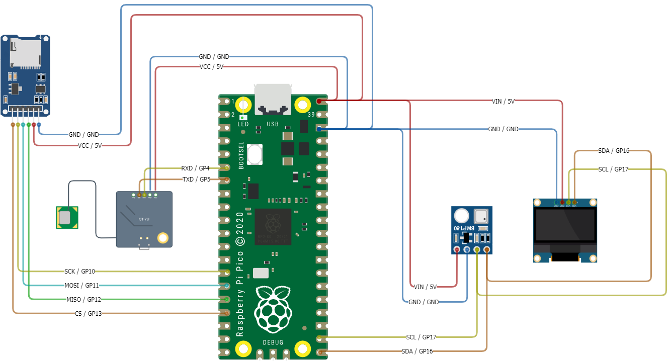
Wire All the Modules into the Breadboard
IMPORTANT Before wiring your Pico, UNPLUG IT FROM YOUR COMPUTER. If plugged in while wiring, you risk damaging the Pico or SDCard reader.
It is recommended to wire each module in the order listed below. After you wire one module, test the code by uncommenting the code block for that module. By taking this approach, we can debug any modules that may not be working as expected using the troubleshooting techniques learned in pervious lessons.
| Module/Controller Pin | Description | Breadboard (BB) / Pi Pico Pins |
|---|---|---|
| SSD1306 OLED Display | ||
| GND | (Ground): Connect to the ground pin on Pico | GND (38) |
| VCC | (Voltage Common Collector): Provides power to the module. Connect to the 3.3V pin on Pico | 3.3V (36) |
| SCL | (Serial Clock): Accepts clock pulses from the Pico to synchronize data transmission | GP10 (17) |
| SDA | (Serial Data): Used for data exchange | GP16 (16) |
| SD Card | ||
| VCC | (Voltage Common Collector): Provides power to the HW-125. | VBUS 5v (40) |
| GND | Ground | GND (38) |
| SCK | (Serial Clock): Accepts clock pulses from the Pico to synchronize data transmission | GP10 (14) |
| MOSI | (Master Out Slave In): SPI input to microSD card module | GP11 (15) |
| MISO | (Master In Slave Out): SPI output from the microSD card module | GP12 (16) |
| CS | (Chip Select): Control pin used to select one (or set) of devices on the SPI bus | GP13 (17) |
| Pressure Temperature Sensor | ||
| GND | Ground | GND (38) |
| VIN | (Voltage In): Provides power to the BMP-180. | 3.3V (36) |
| SCL | (Serial Clock): Accepts clock pulses from the Pico to synchronize data transmission | GP17 (19) |
| SDA | (Serial Data): Used for data exchange | GP16 (18) |
| GPS Sensor | ||
| GND | Ground | GND (38) |
| VCC | (Voltage In): Provides power. | 3.3V (36) |
| PPS | (Pulse Per Second): Assists with synchronization | N/A |
| TXD | (Transmit): Transmission pin used for serial communication | UART1 RX / GP5 (7) |
| RXD | (Receive): Receiver pin used for serial communication | UART1 TX / GP4 (6) |
Main program
The steps in this section will use the previous hardware and driver sections to allow writing/reading to/from a CSV file, reading GPS data, and pressure/temperature data. This code also incorporates better exception handling and performs a diagnostic on startup, displaying the diagnostic to the OLED display module. The code example for this lesson is located in Lesson 8: /src/main.py.