StratoLab
Lesson 4: Sensing the Environment
Prerequisites
- To complete this lesson, you need to be able to connect your microcontroller to your computer and upload a program to it using the IDE. If you are not able to do that, please complete Lesson 1 before continuing.
- You should have a good understanding of how to write code in the declaration, setup, and loop sections of a program. It is recommended to complete Lesson 2.
Objectives
Students will:
- Learn the basic principles of environmental sensing
- Learn how the I2C protocol is used for peripheral communication
- Write a program to measure temperature and pressure
Materials
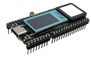
- Heltec Wireless Tracker
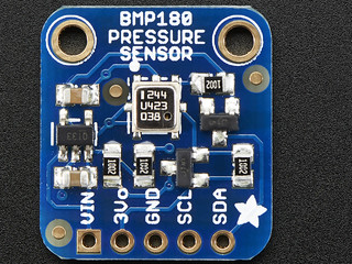
- BMP180 Sensor
- Breadboard
- Jumper Wires
Activity
Understanding the Tech
The BMP180 makes clever use of a phnomenon called piezoresistance. This is when a material changes its electrical resistance when it is strained - stretched or compressed. The engineers who designed the BMP180 made a sensor that is strained in different ways when the temperature changes and when the air pressure changes. A sensitive electronic circuit then measures this change in resistance and does some calculations to find the temperature and pressure. More information on how the pressure calculation works can be found here. The temperature calculation is similar and uses a piezo element that changes as it gets hotter and colder.
Once the BMP180 sensor has calculated the temperature and pressure, it needs to send this data to the microcontroller. The sensor and microcontroller must both agree on the way to send this data over a few wires. This is called a protocol. Imagine that you were on a ship and needed to send a message to another ship by blinking a spotlight. How would you do it? You might both agree in advance to use Morse code - one of the most oldest protocols for sending text from one place to another. The BMP180 could in fact use Morse code, but instead it uses a more efficient protocol called the Inter-Integrated Circuit protocol or simply I2C. More details on how I2C works can be found on this SprakFun tutorial but the basic idea is that the protocol uses two wires - one for data, called the SDA wire, and one for a clock signal, called the SCL wire.
Communicating with the BMP180 Sensor
Getting the microcontroller to communicate with the BMP108 is easiest if we make use of some code that others have already written to take care of the I2C communication to the BMP180. This is called “library” code.
-
Open the Arduino IDE and start a new program.
- Erase any existing text, then add the following initialization code:
#include <Arduino.h> // library code for the Arudino IDE #include <Wire.h> // library code for the I2C protocol #include <BMP180.h> // library code for the BMP180 sensor #define SDA 46 // set the correct pins for I2C #define SCL 45 BMP085 bmp; // create a sensor object (085 is not a typo) void setup() { Wire.begin(SDA, SCL); // set up the I2C protocol to communicate with sensors Serial.begin(115200); // set up the serial protocol to communicate with laptop bmp.begin(); // start communicating with the BMP180 sensor delay(1000); // pause to allow all initialization to finish scan(); // find all connected I2C devices } - Add the following function below the setup function. This code will help us verify that the sensor is wired correctly. Is is called from the ```setup`` function. Can you see where? As a bonus, the function also finds any other devices that are connected using I2C. Look it over and see if you can figure out how it works.
void scan(){ Serial.println("Scanning all I2C addresses..."); for(int address = 1; address < 127; address++ ){ // try to communicate to this address Wire.beginTransmission(address); byte error = Wire.endTransmission(); // a reply of 0 indicates a successful connection if (error == 0) { Serial.print("I2C device found at address 0x"); Serial.println(address,HEX); } } Serial.println("done"); } - Finally, add this
loop()code. It does not have any comments to explain how it works, but you should be able to finure it out without much trouble. A “double” variable is simply a programming term for a number with a decimal place. (Your mentor may be able to explain why it is called that.)void loop(){ double tempC =bmp.readTemperature(); Serial.print("Temperature = "); Serial.print(tempC); Serial.println(" *C"); int press = bmp.readPressure(); Serial.print("Pressure = "); Serial.print(press); Serial.println(" Pa"); Serial.println(); delay(3000); } - The first time you compile your code, it may tke 5 minutes or more. To make the best use of your time, click the “Compile” button - the check mark - to have the Arduino IDE work on compiling while you work on wiring the sensor. You do not need to have the microcontroller pullged in to compile the code.
Wiring the Sensor
The BMP180 needs a total of four wire connections - power, ground, SDA and SCL.
-
Before placing the BMP180 onto the breadboard, read the pin labels that are on the bottom of the sensor. These will be hidden once you place the sensor, so make a sektch on paper showing which pin is which when seen from the top. Have your mentor or instructor double check your sketch before continuing. If you mix up the wire connections, you could destroy the sensor in less than a second! The sketch will help you make sure your wiring is correct.
-
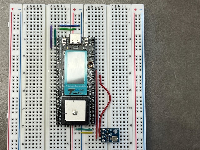
Unplug the microcontroller from power and USB. Place the BMP180 onto the breadboard slightly below the microcontroller. Place it so that the four pins of the BMP180 are in four different rows of the breadbaord.
-
Connect a jumper wire from the BMP180 VIN pin to the red “power” rail of the breadboard. Also connect the same red power rail to the 3.3V pin on the microcontroller. (It is the 3rd pin down on the left side.)
-
Connect a jumper wire from the BMP180 GND pin to the blue “ground” rail of the breadboard. Also connect the same blue ground rail to the GND pin on the microcontroller. (It is the 4th pin down on the left side.) Refer to the photo below. Notice that the circuit is using the power and ground rails that run directly below the mocrocontroller. You may also use the rails on the left or right edge of the board.
-
Connect a jumper wire from the SDA pin of the sensor to pin 46 on the microcontroller. Also connect a jumper wire from the SCL pin of the sensor to pin 45 on the microcontroller.
-
Check your wiring with the photo below. Then, have someone else like your mentor check your wiring. You can use the right or left red and blue rails instead of the center ones, but make sure that power and ground from the microcontroller is reaching the BMP180.
-
Plug the microcontroller into your laptop and upload the code using the right arrow button. Test the temperature sensor by wrming it with your hand. Check the internet to see if the barometric pressure is similar to what is reported in today’s weather. (You may need to convert units.)
Using the LED Display
- The model of LED screen on the microcontroller board is an ST7735. Like the sensor, it is easiest to make use of some library code to communicate with the LED screen. Add these two lines to the initialization section of your code:
#include "HT_st7735.h" HT_st7735 screen; - Add this line inside your setup function:
screen.st7735_init(); - Add lines similar to these just before the
delay(3000);line:screen.st7735_fill_screen(ST7735_BLACK); String tempInfo = (String)tempC + " degC"; screen.st7735_write_str(0, 0, tempInfo); - Compile and upload your code. See if you can figure out how to add more text or shapes in different places to the LED display. As hints, here are some lines that will compile successfully: ``` screen.st7735_draw_pixel(160, 50, ST7735_RED); screen.st7735_write_str(20, 50, “Hello!”, Font_11x18, ST7735_YELLOW, ST7735_CYAN); //also Font_7x10 or Font_16x26
Still stuck? With your mentor, take a look at the solution code linked on Github.