StratoLab
Lesson 2: Arduino Basics
Blink the built-in LED and create a LED array
Pre-requisites:
Objectives:
- How to download the Arduino IDE software
- How to connect to the Arduino to your computer
- Make the onboard LED blink
- Create and LED array and blink it in sequence
Parts required:
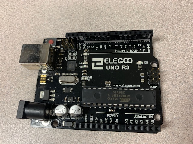
- Arduino
- PC or laptop, in the guide below we will be downloading the Arduino IDE
- If using chromebooks or you cannot install the above application, try the Web version of arduino studio to run the IDE from the web!
- Youll need to login to use the web app
- You ponly get 25 code pushes per day so use them wisely
What you will be learning:
- How to download the Arduino IDE software
- How to create a new Arduino Sketch project
- How to write code in the Arduino IDE and upload it to the Arduino in order to blink the LED
Video Walk-through
In addition to the reading below, you can watch this video for guidance!
Unable to download?
If you are unable to download the software due to access issues or hardware restricitons, feel free to use the Online IDE. Follow these Setup instructions to create an account and configure the plugin.
Helpful video shortcuts
- Downloading the Arduino IDE software
- How to connect the Arduino to your PC
- What is a COM port?
- Where is the onboard LED?
Working project
Copy and paste this code into your sketch and run it
void setup() {
  // put your setup code here, to run once:
  pinMode(13,OUTPUT);
}

void loop() {
  // put your main code here, to run repeatedly:
  digitalWrite(13,HIGH);
  delay(100);
  digitalWrite(13,LOW);
  delay(900);
}
Troubleshooting
- Is the USB cord plugged in to both the Arduino and the pc/laptop?
- Is the board selected from dropdown in the Arduino IDE?
Ready for more?
Next we will configire three LEDs to blink in sequence. You will need a single LED and a resistor, let’s learn about both of them first. Below is an LED (Light Emitting Diode). Notice that one leg of the LED is longer than the other. The longer leg is the positive (+) side and the shorter leg is the negative (-) side. This is important to remember. Wiring the LED backward wil not allow it to light up (and could destroy it).
<img src=assets/images/LED.jpg width=”250” >
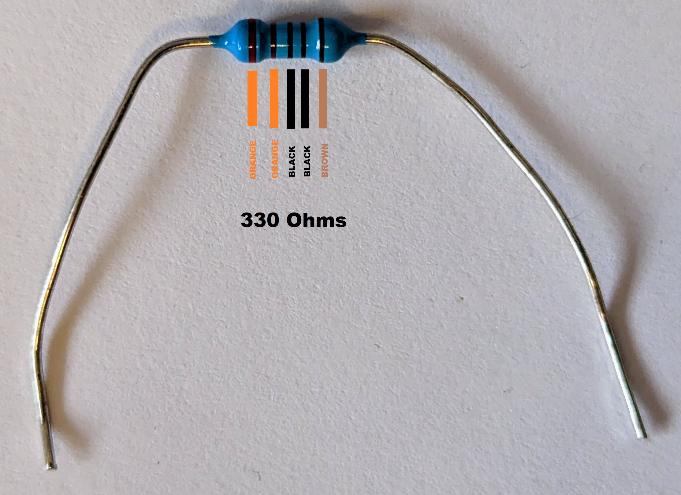
You will also need a resistor, which is pictured below. The more resistance provided by the resistor, the less current is allowed to flow to the LED. More current means a brighter light, less current means a dimmer light. If you were to skip the resistor (or use one with too little resistance), you will damage both the LED and the board because the LED would get more current than it can handle and the board would be sending more current than it can support through that pin. The resistor is important to protect the circut from overloading.
Notice the colored bands on the resistor, these indicate the amount of resistance that will be provided. It is admittedly a pretty cryptic system, but resistors are small so it is what it is. You can decode the bands using online resitor color code calculators. For our needs we will use a resistor that is between 220 and 330 Ohms. The resistor pictured below is 330 Ohms and has band colors Orange, Orange, Black, Black, Brown.
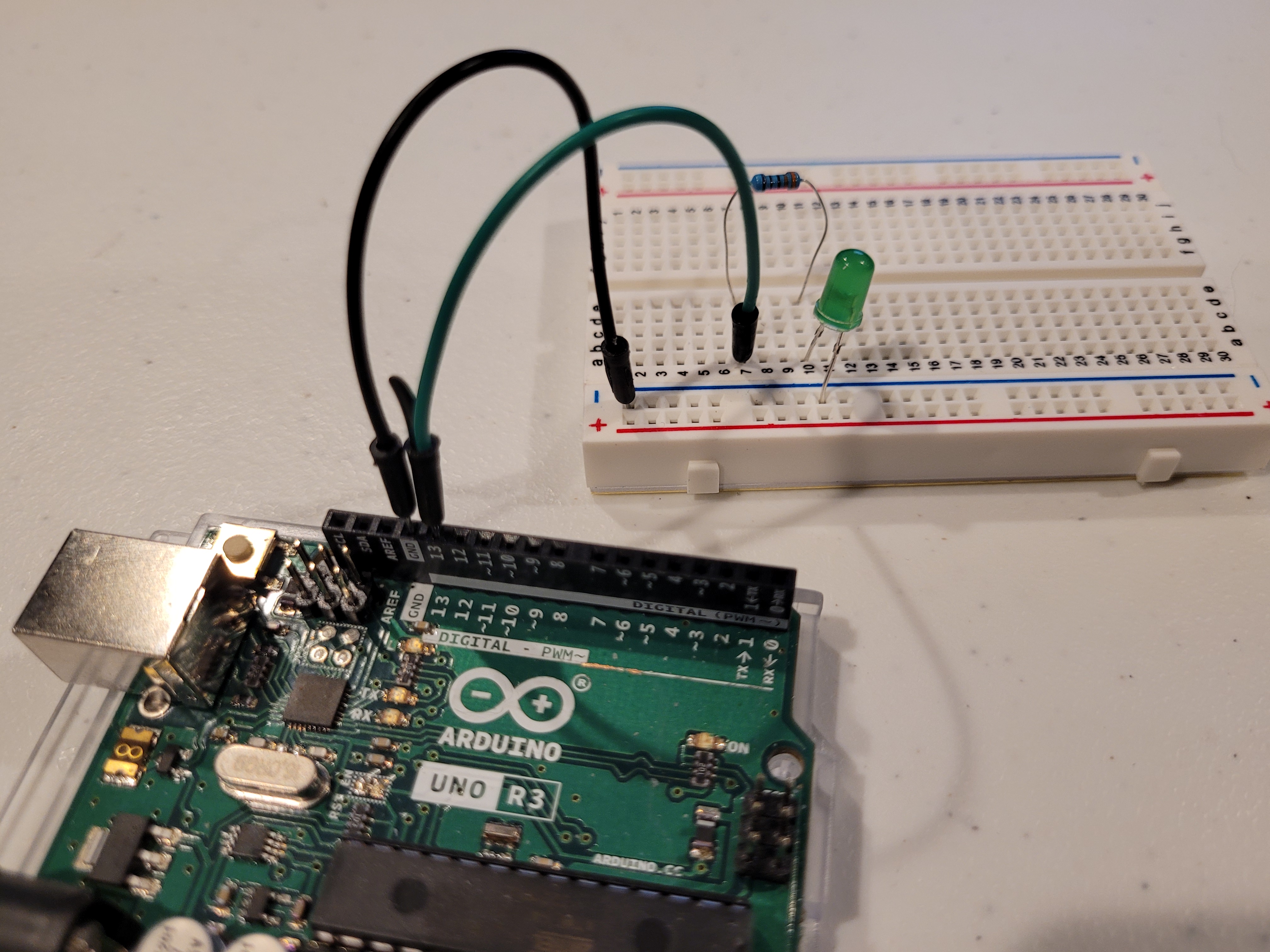
Ok, let’s wire up the breadboard with the LED and resistor!
-
First, we need to connect one of the GND (“ground”) pins to the negative (-) bar on the breadboard. You simply need to insert a wire into the GND pin on the board and then to any hole in the negative bar on the breadboard. In the image below, this is the black wire. This will enable us to gound our circuiut later.
- Next, a wrie from the 13 pin of the board to a line on the bread board (A7 in this example).
- Then connect a resistor from that line to another further down the line (E7 to E10). Don’t be afraid to give yourself some room.
- Next, connect the positive (+) side of your LED to the resistor, through the breadboard, by inserting the long leg of the LED into another hole on the same row you just connected the resistor. The negative (-) side of the LED will be put directly into the negative (-) bar on the breadboard. When you are done, your setup should look like the picture below.
Working project
- Copy and paste this code into your sketch and run it
void setup()
{
  // Green LED
  pinMode(13,OUTPUT);
}

void loop()
{
  // Blink your LED
  digitalWrite(13, HIGH);
  delay(500);
  digitalWrite(13, LOW);
  delay(500);
}
Congratulations, you have created your first complete circuit!! In the next step, we’ll write some code and wire up more LEDs to blink in squence.
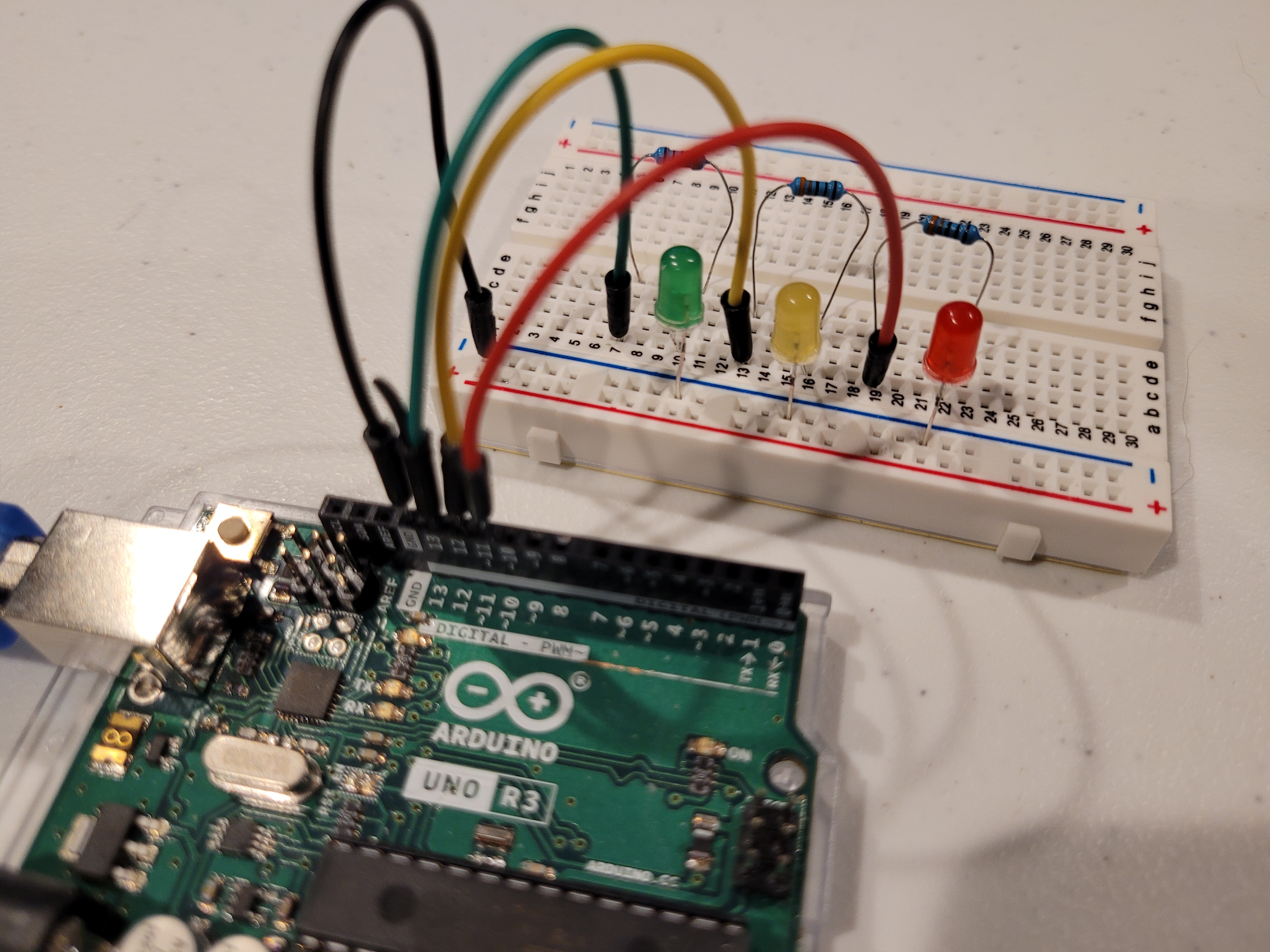
Using the same principles you learned above, wire two more LEDs, connecting them to PIN 12 and PIN 11. Give yourself plenty of room when placeing the new LEDs. The image below is what the final circuit should look like. Be careful that none of the resistor or LED wires are touching each other, it can get pretty crowded on the breadboard if you are not careful.
Working project
- Copy and paste this code into your sketch and run it
void setup()
{
  // Green LED
  pinMode(13,OUTPUT);
  // Yellow LED
  pinMode(12,OUTPUT);
  // Red LED
  pinMode(11,OUTPUT);
}

void loop()
{
  // Cycle through the LEDs and blink them
  digitalWrite(13, HIGH);
  delay(500);
  digitalWrite(13, LOW);
  delay(500);
  digitalWrite(12, HIGH);
  delay(500);
  digitalWrite(12, LOW);
  delay(500);
  digitalWrite(11, HIGH);
  delay(500);
  digitalWrite(11, LOW);
  delay(500);
}
Congratulations! You have successfully looped a multi LED circut.
Need help?
Watch the walk-through video for guidance!